Ophthalmic ultrasonography uses high-frequency sound waves, which are transmitted from a probe into the eye. As the sound waves strike intraocular structures, they are reflected back to the probe and converted into an electric signal. The signal is subsequently reconstructed as an image on a monitor, which can be used to make a dynamic evaluation of the eye or can be photographed to document pathology.
Sound is emitted in a parallel, longitudinal wave pattern, similar to that of light. The frequency of the sound wave is the number of cycles, or oscillations, per second, measured in hertz (Hz). For sound to be considered ultrasound, it must have a frequency of greater than 20,000 oscillations per second, or 20 KHz, rendering it inaudible to human ears.
[3] The higher the frequency of the ultrasound, the shorter the wavelength (distance from the peak of one wave to the peak of the next wave). A direct relationship exists between wavelength and depth of tissue penetration (the shorter the wavelength, the more shallow the penetration). However, as the wavelength shortens, the image resolution improves.
Given that ophthalmic examinations require little in the way of tissue penetration (an eye being 23.5 mm long on average) and much in the way of tissue resolution, ultrasound probes used for ophthalmic B-scan are manufactured with very high frequencies of about 10 million oscillations per second, or 10 MHz. In contrast, ultrasound probes used for purposes such as obstetrics use lower frequencies for deeper penetration into the body, and, because the structures being imaged are larger, they do not require the same degree of resolution. Recently, high-resolution ophthalmic B-scan probes (ultrasound biomicroscopy or UBM) of 20-50 MHz have been manufactured that penetrate only about 5-10 mm into the eye for incredibly detailed resolution of the anterior segment.
[4]
Velocity
The velocity of the sound wave is dependent on the density of the medium through which the sound travels. Sound travels faster through solids than liquids, an important principle to understand since the eye is composed of both. There are known velocities of different components of the eye, with sound traveling through both aqueous and vitreous at a speed of 1,532 meters/second (m/s) and through the cornea and lens at an average speed of 1,641 m/s.
[3]
Reflectivity
When sound travels from one medium to another medium of different density, part of the sound is reflected from the interface between those media back into the probe. This is known as an echo; the greater the density difference at that interface, the stronger the echo, or the higher the reflectivity.
[3]
In
A-scan ultrasonography, a thin, parallel sound beam is emitted, which passes through the eye and images one small axis of tissue; the echoes of which are represented as spikes arising from a baseline. The stronger the echo, the higher the spike. For example, the vitreous is less dense than the vitreous hyaloid, which, in turn, is much less dense than the retina. Therefore, the spike obtained as the sound strikes the interface of the vitreous and hyaloid is shorter than the spike obtained when the sound strikes the hyaloid-retinal interface.
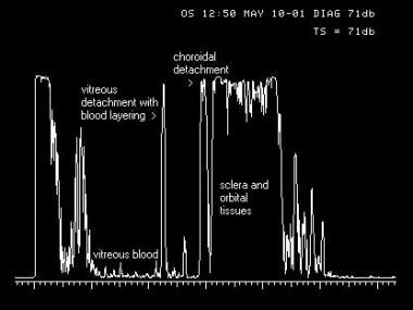 A-scan image of an eye with a traumatic vitreous hemorrhage, posterior vitreous detachment layered with blood, and peripheral choroidal detachment. A thin, parallel sound beam passes through the eye, imaging one small point through the tissues as it passes. The echoes returned to the probe in A-scan mode (left) are converted to spikes that arise from baseline, the amplitude of which is determined by the strength of the echo, giving the examiner information regarding the density of the tissues.
In B-scan ultrasonography, an oscillating sound beam is emitted, passing through the eye and imaging a slice of tissue; the echoes of which are represented as a multitude of dots that together form an image on the screen (see Image 2). The stronger the echo, the brighter the dot. Using the same example, the dots that form the posterior vitreous hyaloid membrane are not as bright as the dots that form the retinal membrane. This is very useful in differentiating a posterior vitreous detachment (a benign condition) from a more highly reflective retinal detachment (a blinding condition).
See the image below.
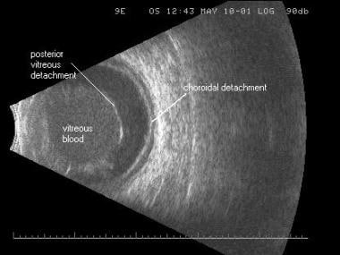 B-scan image of the same traumatic vitreous hemorrhage, posterior vitreous detachment, and low-lying choroidal detachment. An oscillating sound beam passes through the eye, displaying a slice of tissue in one image. The echoes returned to the probe are displayed as a series of dots that form an image, the brightness of which is determined by the strength of the echo, allowing the examiner to determine the density of the tissue for diagnostic purposes.
Angle of incidence
The angle of incidence of the probe is critical for both A-scan and B-scan ultrasonography. When the probe is held perpendicular to the area of interest, more of the echo is reflected directly back into the probe tip and sent to the display screen. When held oblique to the area imaged, part of the echo is reflected away from the probe tip and less is sent to the display screen.
[3] The more oblique the probe is held from the area of interest, the weaker the returning echo and, thus, the more compromised the displayed image.
On A-scan, the greater the perpendicularity, the more steeply rising the spike is from baseline and the higher the spike. On B-scan, the greater the perpendicularity, the brighter the dots on the surface of the area of interest. The size and shape of the surface at each interface also affect that reflection. When a surface is large and flat and the probe is held in a perpendicular manner, the complete echo returns to the probe for display. If the surface is curved or irregular in shape, part of the echo is reflected away and less echo returns to the probe for display, even when the probe is held in a perpendicular manner. If the interface is very small, as in a vitreous opacity, so much of the sound is scattered that the returning echo is very weak.
Because various parts of the eye and various pathologies are different in size and shape, understanding this concept and anticipating the best possible display for that eye are important. Perpendicularity to the area of interest should be maintained to achieve the strongest echo possible for that structure.
Absorption
Ultrasound is absorbed by every medium through which it passes. The more dense the medium, the greater the amount of absorption.
[3] This means that the density of the solid lid structure results in absorption of part of the sound wave when B-scan is performed through the closed eye, thereby compromising the image of the posterior segment. Therefore, B-scan should be performed on the open eye unless the patient is a small child or has an open wound. By performing on the open eye, the patient is also now able to look in extreme down gaze, which is impossible when the eye is closed and rotated upward. Because the probe is placed directly on the conjunctiva, and because the probe face and the globe must not be separated by any air, a liberal amount of gel-type tear solution should be placed on the probe face prior to examination. Care should be taken that only those solutions designed for ophthalmic use are incorporated so that eye irritation does not occur.
Likewise, when performing an ultrasound through a dense cataract as opposed to the normal crystalline lens, more of the sound is absorbed by the dense cataractous lens and less is able to pass through to the next medium, resulting in weaker echoes and images on both A-scan and B-scan. For this reason, the best images of the posterior segment are obtained when the probe is in contact with the conjunctiva rather than the corneal surface, bypassing the crystalline lens or intraocular lens implant. Finally, when calcification of tissue is present, there is so much absorption and such a strong reflection of the echo back to the probe that there is no signal posterior to that medium. This is referred to as shadowing.
See the image below.
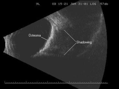 Shadowing caused from sound absorption by the calcium within a choroidal osteoma. Calcium is so dense that no sound can penetrate it to travel on to the next structure.
Instrumentation
Ophthalmic ultrasound instruments use what is known as a pulse-echo system, which consists of a series of emitted pulses of sound, each followed by a brief pause (microseconds) for the receiving of echoes and processing to the display screen. The amplification of the display can be altered by adjusting the gain, which is measured in decibels (dB). Adjusting the gain in no way changes the frequency or velocity of the sound wave but acts to change the sensitivity of the instrument’s display screen. When the gain is high, weaker signals are displayed, such as vitreous opacities and posterior vitreous detachments. When the gain is low, the weaker signals disappear, and only the stronger echoes, such as the retina, remain on the screen. However, there is better resolution, or detail, of the area of interest when the gain is lowered. Typically, all examinations begin on highest gain so that no weak signals are missed; then, the gain is reduced as necessary for good resolution of the stronger signals. [3]
Sterile dry eye gel should be dispensed onto the surface of the probe face, which is usually oval in shape and when placed on the anesthetized globe, is represented by the initial white line on the left side of the display screen. The vitreous cavity is displayed in the center of the echogram, and the posterior pole is displayed on the right side of the echogram. There is a marker (usually a dot or line) on the side of the probe handle near its face, on one side of the short end of the oval. Knowing the orientation of the marker at all times is extremely important because it represents the upper portion of the echogram. The back-and-forth motion of the transducer occurs along the long portion of the oval; thus, the slice emitted occurs in the direction of the marker.
In other words, if the area of interest is at the 3-o’clock position, the probe face is held on the globe at the 9-o’clock position with the marker aimed upward. The center of the probe is aiming at the 3-o’clock position, which appears in the center of right side of the echogram, the area of best resolution. The top of the right side of the echogram represents the 12-o’clock position since that is the orientation of the marker, and the bottom of the echogram on the right represents the 6-o’clock position since that is the portion opposite the marker. Therefore, the slice of tissue on the right side of the display is from the 12-o’clock position to the 6-o’clock position, with the 3-o’clock position in the center. If the probe is held at the 9-o’clock position but rotated so the marker is now aimed inferiorly, the 3-o’clock position remains in the center of the display, but now the 6-o’clock position is at the top and the 12-o’clock position is at the bottom.
Anterior Segment Evaluation
Immersion technique
Because the area of best resolution is in the center on the right side of an echogram, examining the anterior segment with a standard 10 MHz contract probe can be accomplished only with the use of a scleral shell. This shifts the anterior segment to the right and into the area of focus of the sound beam, improving resolution of anterior segment pathology. The shell is filled with methylcellulose or some other viscous solution to a meniscus, avoiding air bubbles within the shell. The probe is placed on top of the shell. This produces an echolucent area on the left side of the echogram corresponding to the shell and methylcellulose, and it shifts the anterior segment to the right side of the display screen. [5]
See the image below.
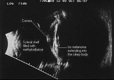 Immersion B-scan image of an iris melanoma extending into the ciliary body. To the left side of the scan is the scleral shell filled with methylcellulose, with the cornea and iris seen centrally and the posterior segment seen on the right.
With contact B-scan, the patient looks toward the pathology, and the probe is held opposite to adequately center the pathology, whereas with immersion B-scan, the patient looks opposite the pathology to center the area of interest directly under the shell. Diagnostic A-scan also can be performed through the shell, directly over the lesion, for tissue differentiation.
High-resolution technique
High-resolution B-scan probes have been developed for higher quality imaging of the anterior segment and have proven to be useful for many pathologies, including lesions of the iris and ciliary body, sulcus-to-sulcus measurements, angle measurements, and imaging lenses. As the frequency of the sound wave increases, the resolution increases, but the depth of tissue penetration decreases. These high-resolution probes range from 20 MHz to 50 MHz, with penetration depths of about 10 mm to 5 mm, respectively; therefore, they may be used only for imaging the anterior segment of the eye. The images rendered from these probes are far superior to that of the standard immersion technique because of the higher resolution. However, the zone of focus with these high resolution transducers is quite small; thus, the examiner must adjust the depth of the transducer in the saline to obtain best image quality.
See the image below.
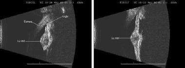 High-resolution B-scan images of an iris melanoma. This imaging requires a separate probe, and it delivers high magnification and superior detail of the small structures of the anterior segment. On the left is a longitudinal, or radial, scan, and on the right is a transverse, or lateral, scan.
These probes may have an external oscillating transducer and can be placed in a special scleral shell, although care must be taken so that the probe never slips into the shell far enough for the transducer to come in contact with the cornea as it oscillates. Another method is to slip the probe into a balloon-type apparatus filled with distilled water to form a protective layer of water between the transducer and the patient’s eye. [3] By placing a small amount of methylcellulose on the vertex of the cover for sound conduction, the tip of the cover rests on the eye directly over the pathology for imaging.
Care should again be taken not to push hard enough against the eye for the transducer to contact the eye or for the bag of water to indent the globe, particularly if scanning to measure the angle. When using these high frequencies, any membrane in front of the transducer causes a degree of sound attenuation; the best image quality is obtained with the scleral shell technique.
For both immersion and high-resolution imaging of the anterior segment, the marker is oriented as with contact scanning for transverse, longitudinal, and axial cuts of the posterior segment. The main difference is that the probe is placed directly overlying the area of interest; depending on manufacturer, the depth of the transducer must be adjusted in the water to achieve maximum focus.
A high-resolution 7.5- 10-MHz or higher linear array ultrasound transducer is used to perform an ocular examination. Emergency ocular ultrasonography is performed using a closed-eye technique. A large amount of standard water-soluble ultrasound transmission gel should be applied to the patient’s closed eyelid so that the transducer doesn’t have to touch the eyelid. Ultrasound gel is not detrimental to eye. The globe should be scanned in both sagittal and transverse planes. Both eyes should be scanned through closed eyelids. The patient is asked to look straight ahead with eyes closed, but without clenching the eyelids. Depth should be adjusted so that the image of the eye fills the screen. Gain should be adjusted to achieve acceptable imaging. Since the eye is a fluid-filled structure, it provides a perfect acoustic window, producing images with excellent detail. The normal eye appears as a circular hypoechoic structure. The cornea is seen as a thin hypoechoic layer parallel to the eyelid. The anterior chamber is filled with anechoic fluid and is bordered by the cornea, iris and anterior reflection of the lens capsule. The iris and ciliary body are seen as echogenic linear structures extending from the peripheral globe towards lens. The normal lens is anechoic. The normal vitreous chamber is filled with anechoic fluid. Vitreous is relatively echolucent in a young healthy eye. Sonographically, the normal retina cannot be differentiated from the other choroidal layers. The evaluation of the retrobulbar area includes optic nerve, extraocular muscles and bony orbit. The optic nerve is visible posteriorly as a hypoechoic linear region radiating away from globe.